Description
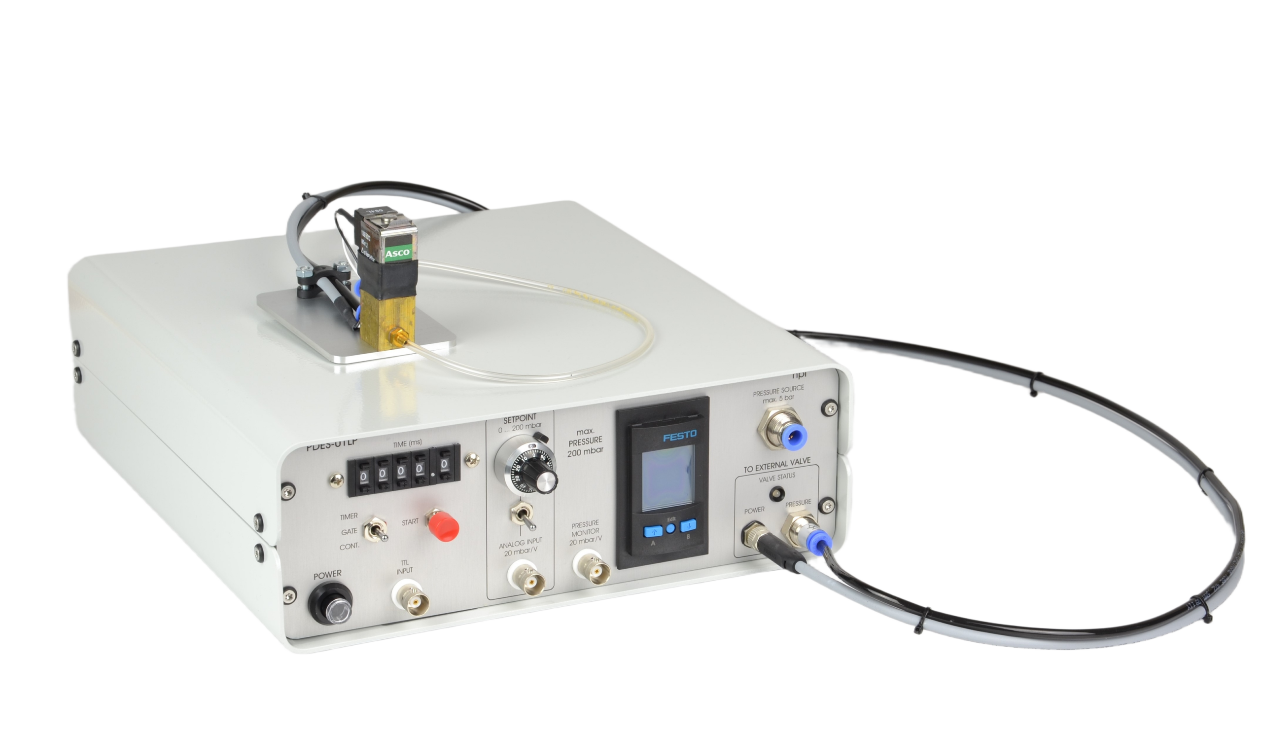
Pressure ejection is a convenient method for applying both ionic and non-ionic solutions from micropipettes. The PDES-01LP, designed by npi Electronic is the latest in the series for pressure ejection of drugs in physiological and pharmacological studies. This special PDES systems is equipped with a low-pressure output (Pmax = 200 mbar). A Digital timer and analog control of the output pressure facilitate the use
of these instruments.
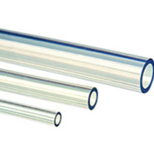
The pressure connectors (quick connect type) are located at the front panel of the instrument. It is equipped with an INPUT coupling (6 mm OD) where the pressure source is connected, an OUTPUT coupling (4 mm OD) where the external valve (PDES-01-BOX) is connected. The injection pressure is preset by a precision pressure regulator. The pressure is displayed on a digital manometer. Additional pneumatic devices (tubes, fittings connectors, filters etc.) are available.
Contact the ALA Scientific Instruments team for more information on the PDES-01LP.
Last Updated on March 3, 2026
Front Panel
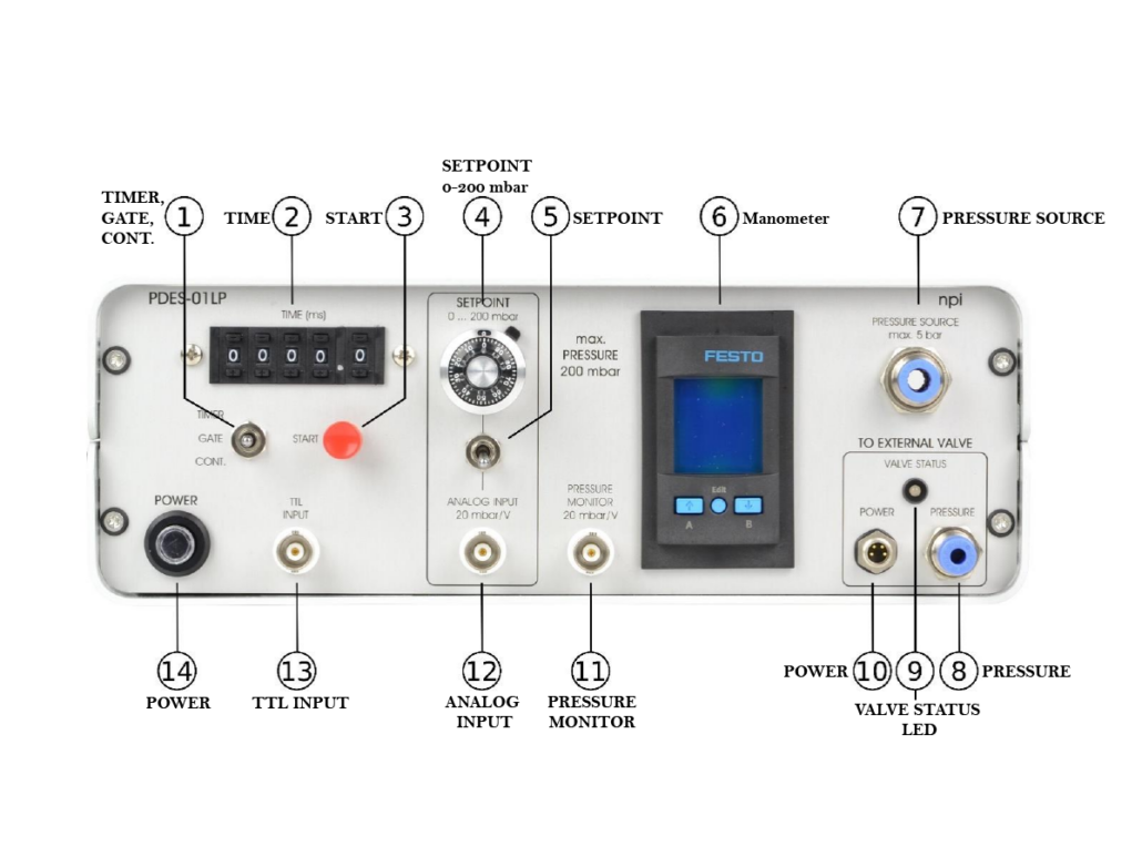
1. TIMER, GATE, CONT. – switch to set operation mode
- In CONT. position (continuous) the application can be controlled manually, i.e. as long as the CONT. position is set, pressure is applied to the pipette.
- In GATE position the duration of the application is determined directly by the duration of the TTL pulse at the TTL INPUT connector (#13).
- In TIMER position the duration is preset by the TIME control (#2)
2. TIME (ms) -Five-digit tumble-wheel switch to set the ejection time (XXXX.X ms) in TIMER mode
3. START – a push button to start operation. Can be used to start ejection in TIMER and GATE mode
4. SETPOINT 0-200 mbar – A 10-turn potentiometer that’s used to set the pressure of the internal pressure controller. (One rotation corresponds to 20 mbar. Maximum is 200 mbar)
5. SETPOINT – selector switch which selects how the set point is set: (Upper position: using the SETPOINT potentiometer, Lower position: using the ANALOG INPUT connector (#12))
6. Manometer – Digital display for the pressure (X.XXXX bar). The pushbuttons under the display are without function
7. PRESSURE SOURCE – Connector for connecting the filtered, dry and oil-free gas source (5 bar max.). This is a quick connector type for 6 mm OD pressure tubing.
- recommend an input pressure of 1 bar more than the maximum output pressure
8. PRESSURE – Connector for connecting the pressure tubing of the external valve on the remote valve plate. The EJECT pressure is supplied to this connector. This is a quick connector type for 4 mm OD pressure tubing.
9. VALVE STATUS LED – This LED indicates the operational status (red light: valve is closed, green light: valve is open)
10. POWER – connector for the electrical connection of the PDES-01-BOX or mircroJECT
11. PRESSURE MONITOR 20 mbar/V – BNC connector monitoring the pressure output. Scaling is 20 mbar/V
- Important: This pressure monitor needs an input pressure to work correctly. If no input pressure is present at the PRESSURE SOURCE connector (#7), this output will give a false reading of -200 mV.
12. ANALOG INPUT 20 mbar/V – BNC connector for monitoring the pressure output. Scaling is 20 mbar/V.
13. TTL INPUT – BNC connector for TTL triggering. ( TIMER mode a TTL HIGH (+5V) signal opens the valve for the time set by #2, GATE mode a TTL HIGH (+5V) signal opens the valve as long as the signal level is HIGH)
14. POWER – Push button to turn POWER on or off
Last Updated on March 3, 2026
Rear Panel
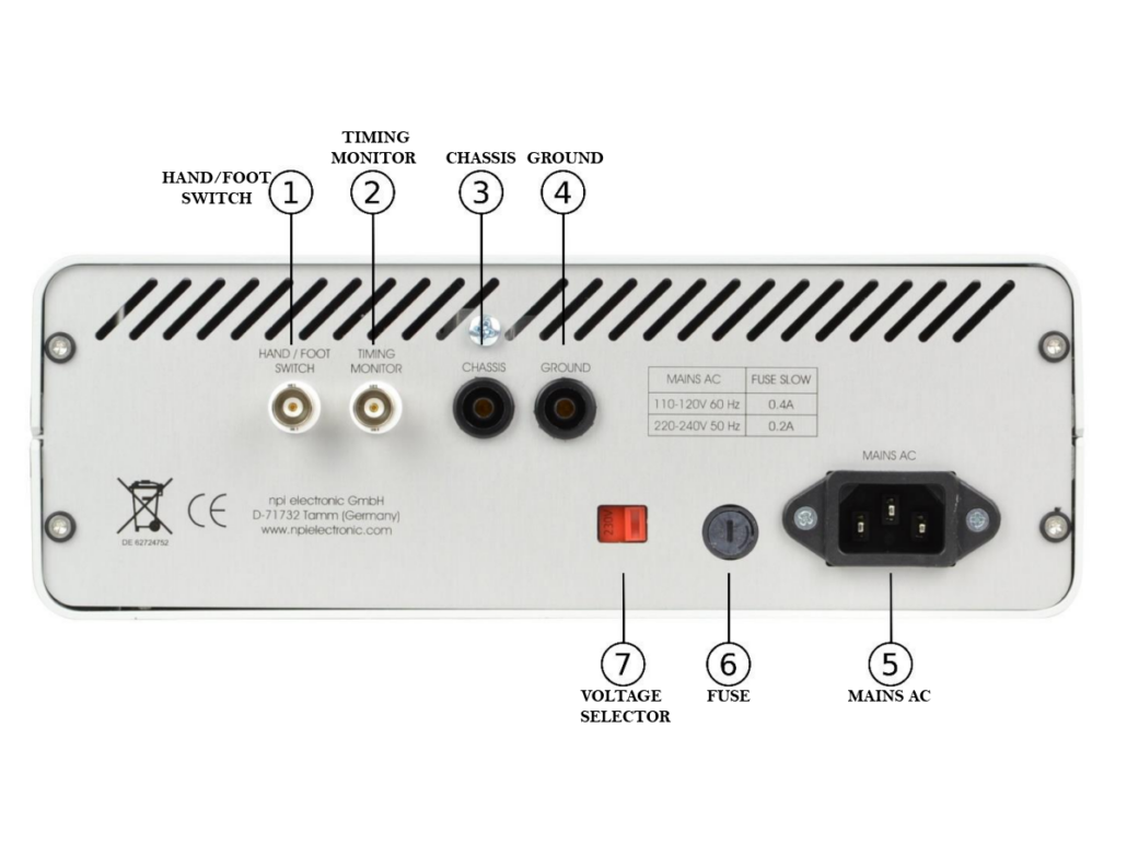
1.HAND/FOOT SWITCH – An optional hand or foot switch for remote triggering can be connected here
2. TIMING MONITOR -This output provides a TTL signal monitoring the valve state: (HIGH = open, LOW = closed)
3. CHASSIS – This connector is linked to mains ground (green/yellow wire, protective earth)
4. GROUND – This connector is linked to the internal system ground which has no connection to the cabinet (CHASSIS) and the mains ground to avoid ground loops
5. MAIN AC – The power cable is connected here
6. FUSE – Unplug the instrument when replacing the fuse or changing line voltage. Turn the knob to open. Replace fuse only with an appropriate specified type
7. VOLTAGE SELECTOR – Rotary switch for selecting the operating voltage (115 V / 230 V)
- Caution: Always switch to the appropriate voltage before connecting the PDES to power
Last Updated on March 3, 2026
Special Features
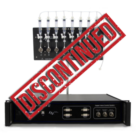
PDES-01-BOX (come included)
This valve is controlled by the PDES-01LP and located on the remote valve plate
*Picture to be added*
MicroJECT (optional accessory)
This special valve which is controlled by the PDES-01LP AND is located in the micro valve pipette
holder
*Picture to be added*
Last Updated on March 3, 2026
Downloads
Manual:
 PEXT-01LP Manual
Last Updated on March 3, 2026